![]()
|
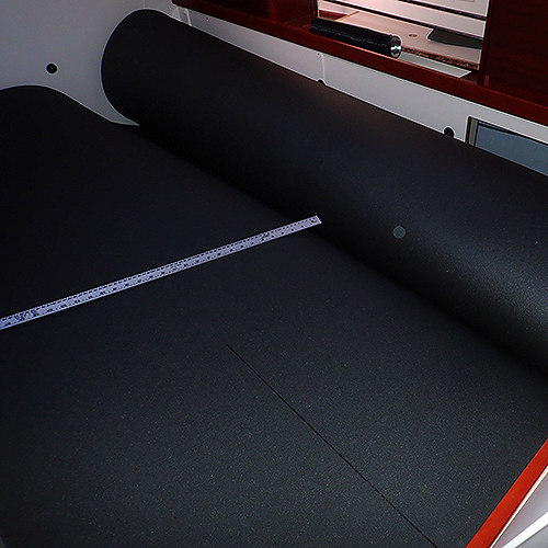
Heat pipe insulation 2020-10-23: This page is under construction but it shows you how we isolated the heathing pipes, cut out a new locker, changed the cover behind the stove and installed a damper (not sure this is the correct word) so we can switch the airflow between saloon and front cabin. There is yet no chronological order in the pictures. If you have any questions, just e-mail me and I'll try to help out. Marco This is a job for at least four hands, especially when you come to the insulation part of the project it will be really great with someone helping with the things. |
|
 If you can, remove the table as it will make life easier when tworking in this area. We started the project by measuring all the supporting structure under neath the saloons bench. We openend all the lockers and used a ruler and the lockers edges as reference points. |
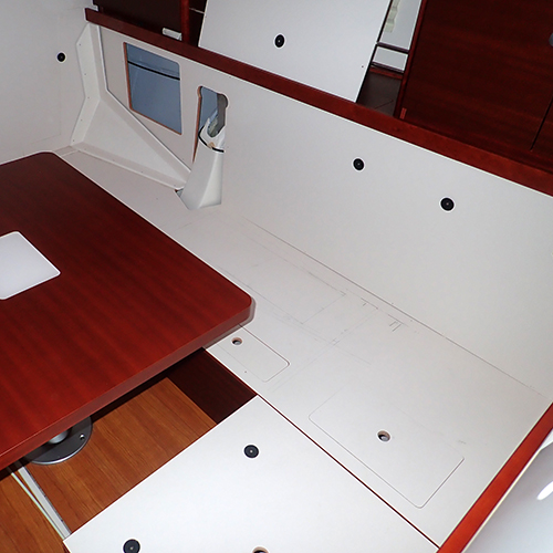
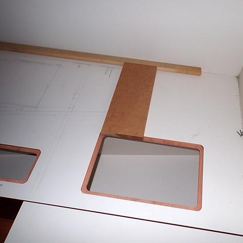
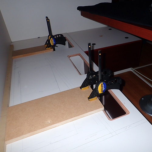
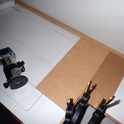
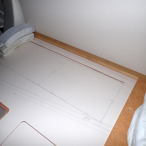
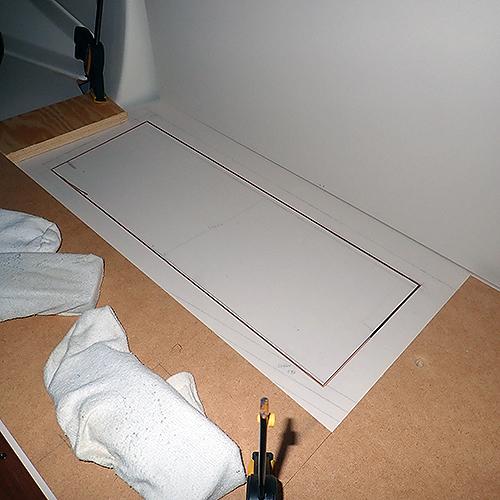
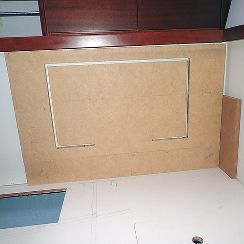
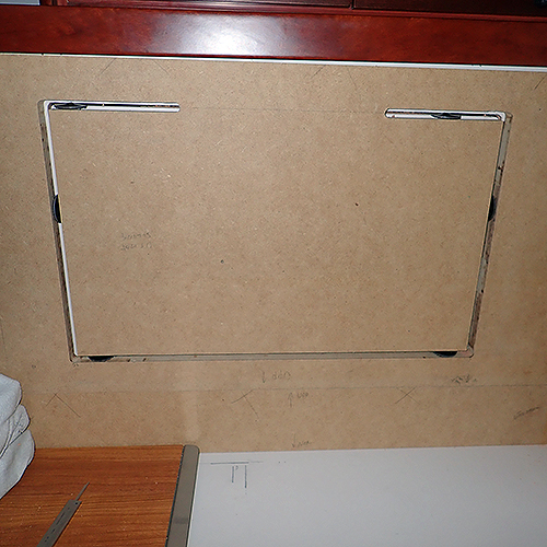
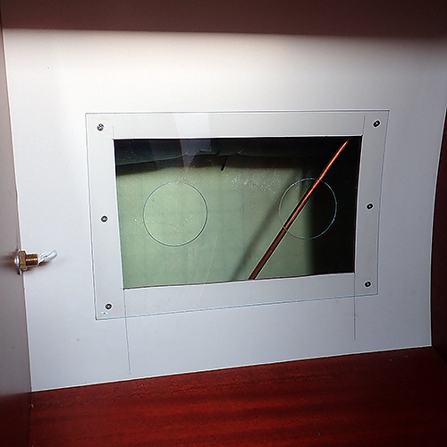
 Here wa have finished the drawing of the supporting structure and decided where the lid should be cut out. Take in consideration the radious of your router plate so you know how close you can get to the back wall. In Älva there was no supporting structure under the bench where the 90 degree angle to the bakc wall is so we decided to keep quite few cm in the back. The piece of MDP is ti secure that we have a contant distance. |
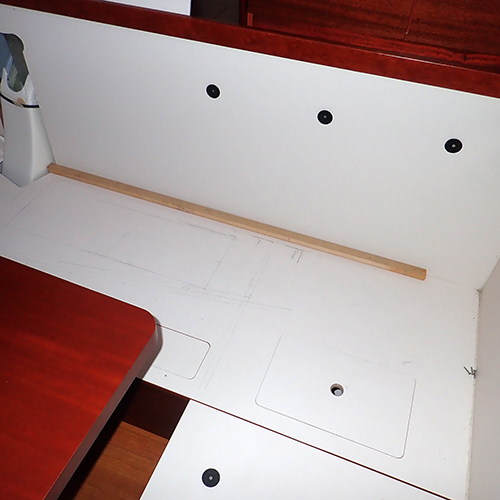
 The new piece of MDF in this picture was used to keep the thinner one in its place but also as a fence when we were cutting out the end of the lid. |
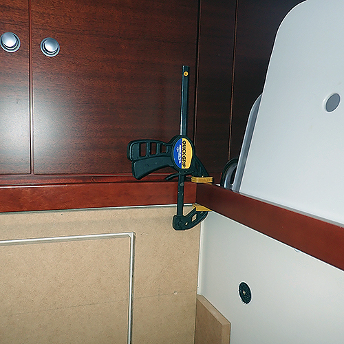
 Measuring where the piece of MDF should be placed. |
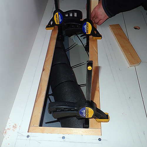
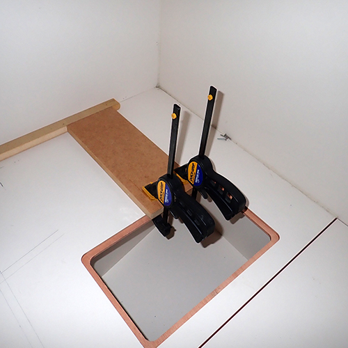 One handed clamps are really great when you work in thigt places or alone. Secure everything as tight as you can in order to assure that the router will not slip or slide.
|
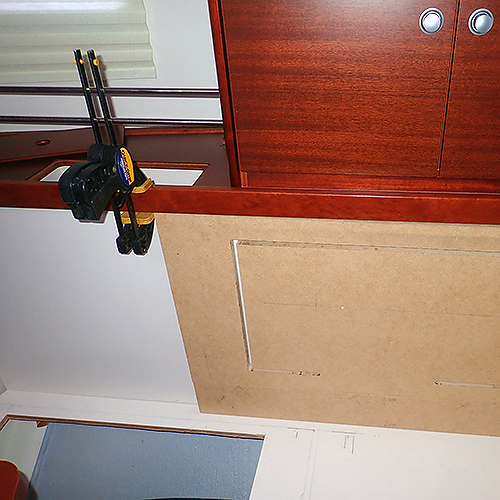
 Measuring the position of the other ends fence for the router cut. |
 Its important to have tested that the router fits in all the places you are going to cut around. At the bottom left you can spot the bulk beam that you must take in consideration when you measure where to cut. |
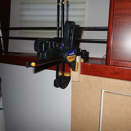
 Clamps, clamps and clams. Very important for a good result. |
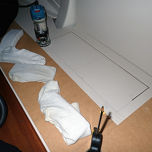
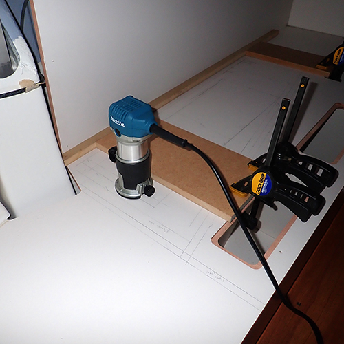 Time for the first cut. As you can see, the router will pass the bulk beam with no problem. |
 Three lead weights á 4 kilo each to ensure that everything really stays in place whilst working with the router. The socks guarantees that no lead marsk will be drawn to the white surface. |
 Remember that you need to have some kind of stopper when you get close to the lids corner. |
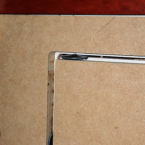
 The first corner is cut. I forgot to tell you that when you use a router you can maximum plunge it as much as the routers diameter. But, since we are using a quite expensive and thin router bits we plunged the bit 1mm at the time. It took some time extra to make the cut but it was definetly worth it. |
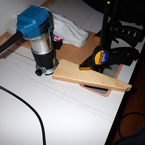
 Adjusting the end stop for cutting out the lids other end. Quite handy to have different sizes of MDF for this project. |
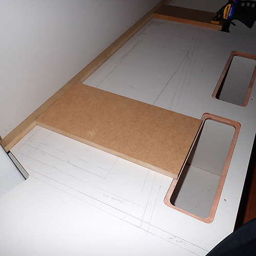
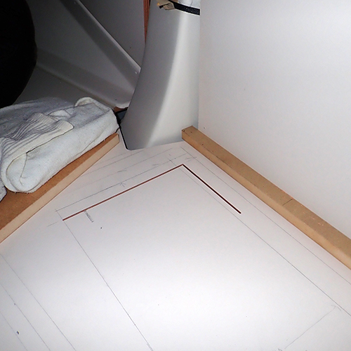
 The back walls cut is now completed |
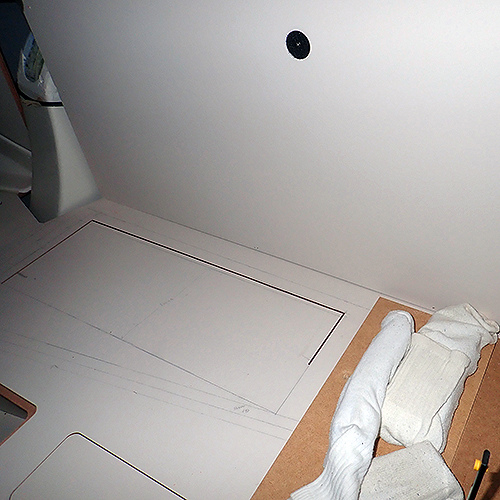 Here we have started to cut out the lids right end. We left it intenially half way as we wanted to see where the remaining long sides cut will cross the right ends cut. |
 The misstake here was that we had the router on the wrong side of the MDF board. As it shows in the next picture, the router can travel upwards and make a wrong cut. The router must always be used ont the side where it wants to travel by its rotation direction. So the MDF with the socks on top (lead weights) should been to the right side of the router. |
 Here you can see how the router started to travel upwards and cut into the lid. some white plastic putty took care of the misshap. |
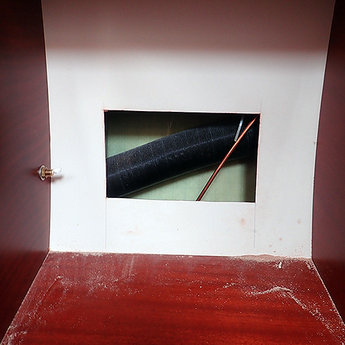
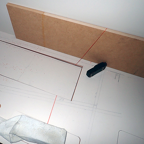 A thin rope (the orange line) was used to support the lid whilst we working on the other end. This prevented the lid from breaking off from the other end. |
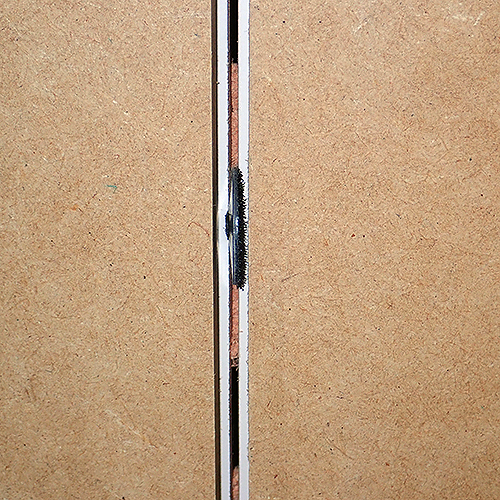
 The plywood is slightly thicker than the 2,5mm router bit we had so it did not reach all the way throug as you can see on the jagged edges. |
 We used a Leatherman to cut open the remaining wood. It had a good bite and was much more easier to saw with. At this stage you want to make diagonal cuts upwards so the plywood wont splint underneath. |
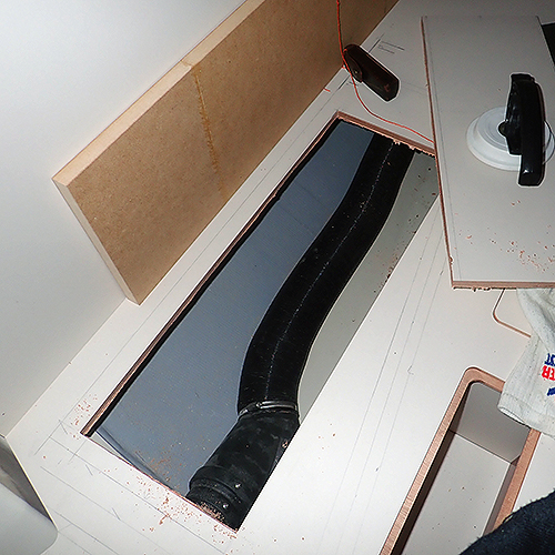
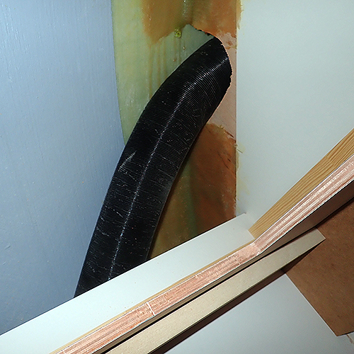
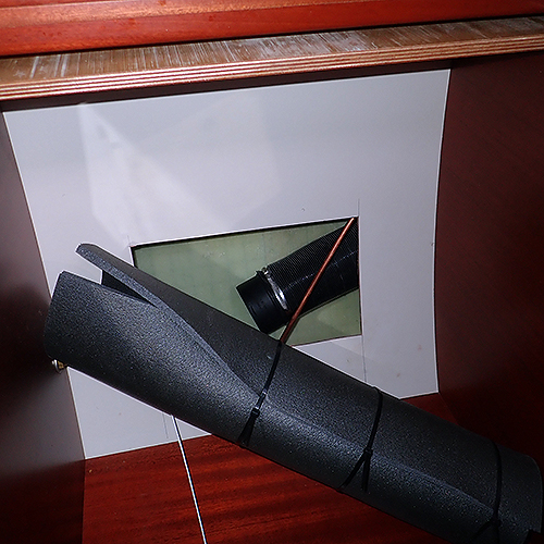
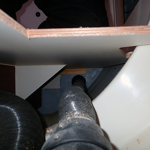 So, whats under the saloon bench? If you look at the bow you see the heating pipe that goes inot the front cabin. |
 Looking at the stern we found this ventilation tube between the fridges bulkhead and the saloon. As you can see, its still taped and kind of compressed.
|
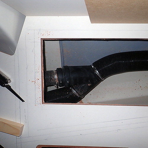
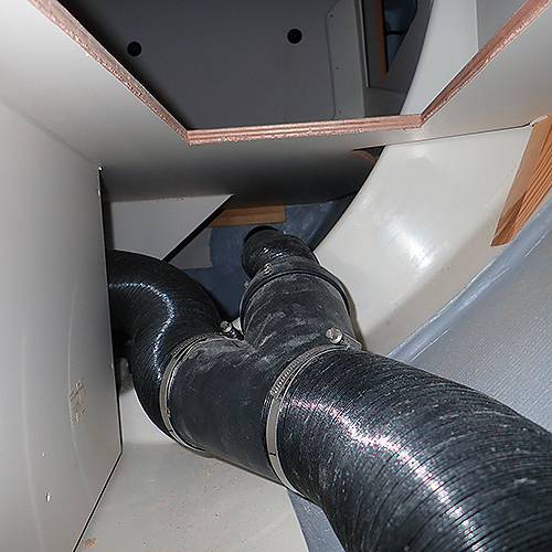 A little bit different angle looking at the bow. Here you see the Y-connector where the air is spearated to the saloon and front cabin. |
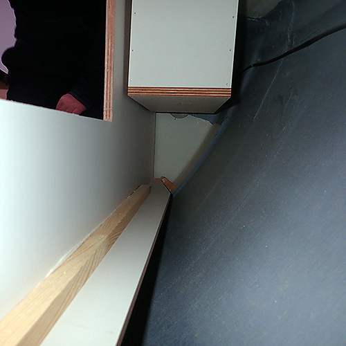
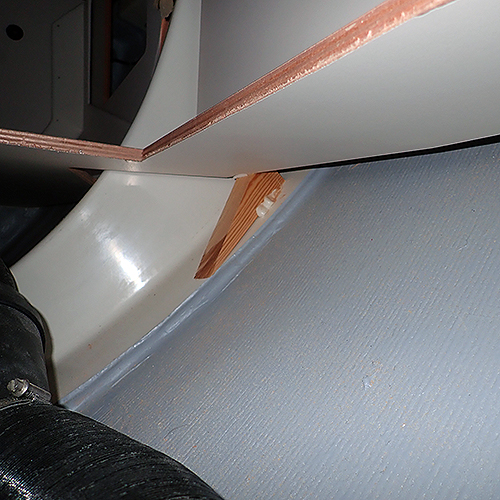 This wedge is all that keeps the back edge of the bench up. So, dont cut the back och the bench too small otherwise it will break. |
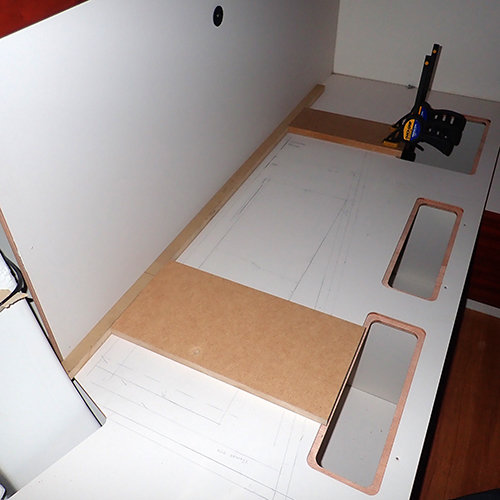
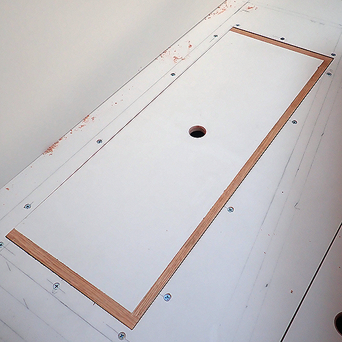
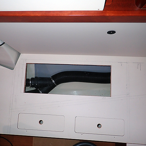 A birds view of the cut out. |
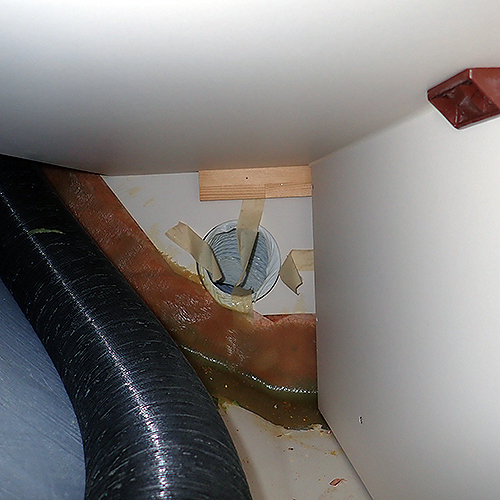
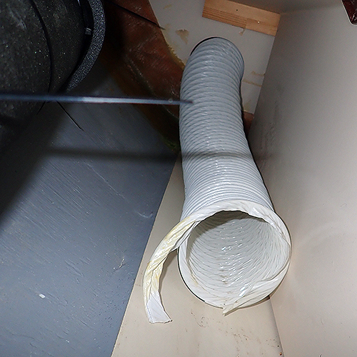
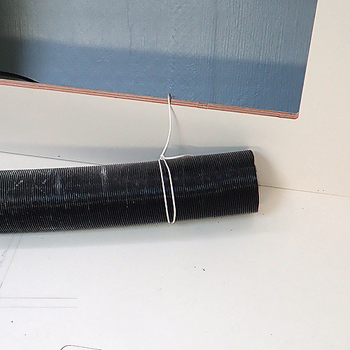
 Lets go back to the white ventilation pipe. The tape was removed and the cut area of the tube wasn't that nicely done. |
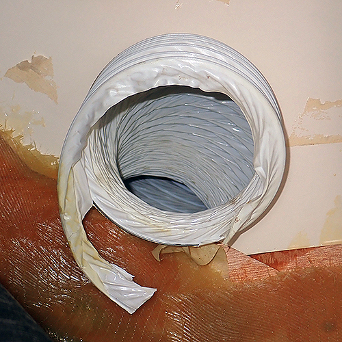 Cloes up of the ventilation tube showing how compressed the tube is as you cant see in it more than few cm.
|
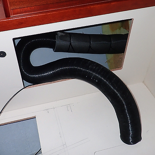
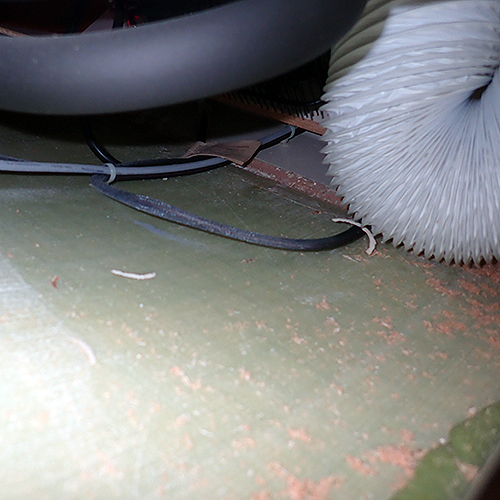 The white pipe is not straight so it did not much for ventilatilation in the fridge compressor space
|
 The fridge compressor ventilation pipe pulled out from the fridge compartment. This is how it should be in our opinion. Quite a difference in lenght, right? We will later on install a small computer fan to increase the airflow to the compressor.
|
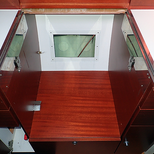
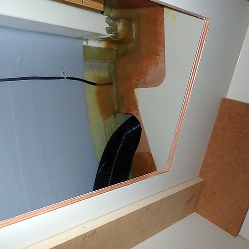
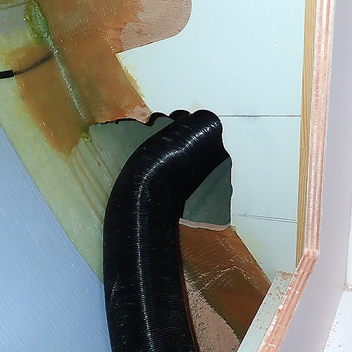
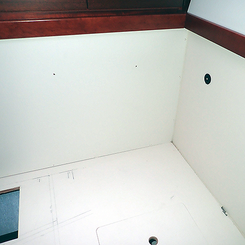 Its impossible to insulate the main heating pipe that is behind the back rest of the saloon so we had to cut out a lid here. |
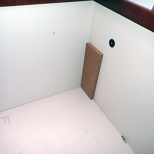 A piece of MDF was used to add some distance to the galleys/fridges back wall. The back and bottom edges of the MDF was cut in 45 degree angle so the Sikalflex could fit in without pushing the MDF out.
|
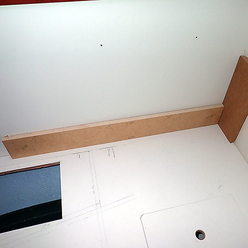 The height was adjusted with and other biece of MDF. You will see soon that there is a reaon for why we need to do it this way. |
 We made a jig for the router to ensure that we would cut everything properly. As you see in the jigs bottom the inner piece is held by the board itself. When doing the final cut you need to rotate the jig 180 degrees and thats why there is the piece underneats, so you can keep the same distance all the time. |
 Clamp is added so the jig won't fall forward. |
 Two clamps to ensure that the jig won't slide. |
 And finally a third clamp to avoid it from falling forward. |
 The round plastic velcro discs that is for the cushions is used as wedges in the cuts as it started to vibrate plus when doing the last final cut we did not want it to fall off inside the back. |
 Close up of a velcro disc used as a vedge. |
 Here you can see that the router did not always cut out the wood in full depth. Why we don't know. Anyway, the Leathermans saw fixed it. Remember, take it easy with the router bits cutting depth. |
 The lid cut out and as you can see to the left on the lid, we had a misshap again! This happend when we rotated the jig and forgot to put the corner MDF in its place. See picture XX |
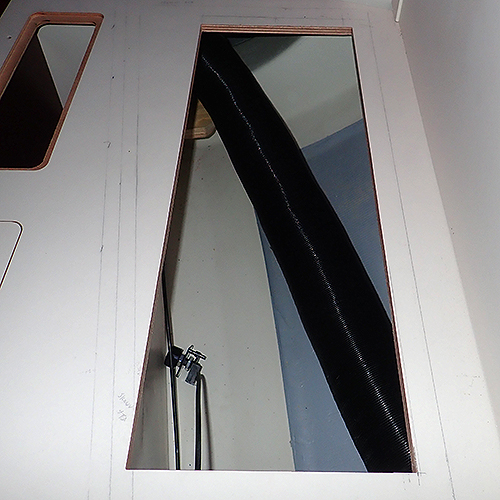
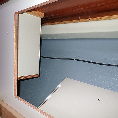 There is quite a lot of space behind the back rest. To the left you see the bottle cabinette that you must take in consideration when deciding where to cut out the back rest lid. |
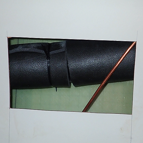
 The pentry/saloon bulkhead with the main heathing pipe. |
 Close up of the pipe that comes from the stern, under the starboard cabins locker stand. |
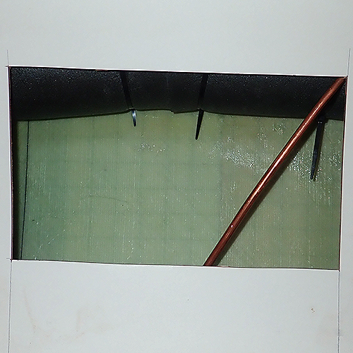
 Here you see how the construction is done of the benches and walls. Stern view. |
 Bow view of the same area. |
 A closer look of the bottle cabinet. |
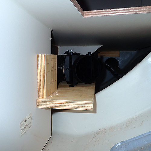 Before we were going to insulate the main pipe we wanted to add a damper so we could adjust the airflow betweenthe front cabin and the saloon as the air flow is not enough when its cold outside. We built a small shelf on which the damper was fitted on. It took some serious time to measure the lenght of the pipe going to the saloon, find the right height for the shelf and then andjust the lenght of the pipe to the front cabin. Too late we figured out that we could opened the front cabin ventilation grid and pulled out the pipe from there and cut it to poroper lenght. Now you can at least avoid out misstake!. |
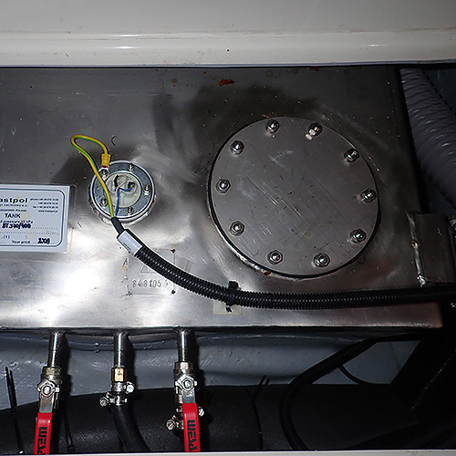
 The damper for directing airflow between saloon and frontcabin. |
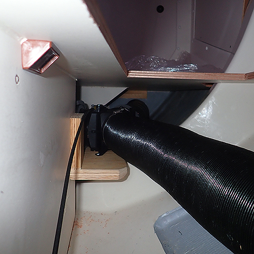
 The main pipe on it splace and the dampers controll unit to the lft on the floor. |
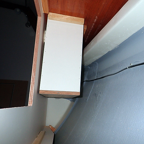
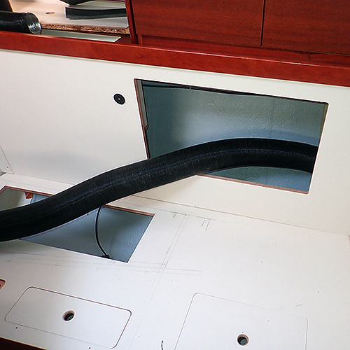
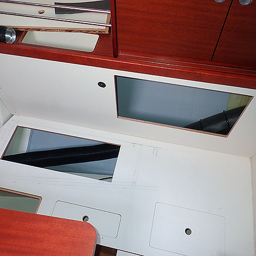
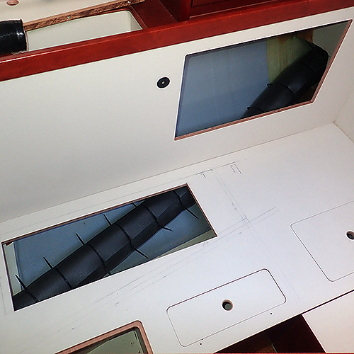
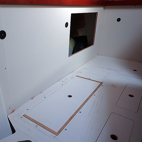
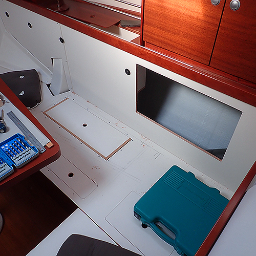
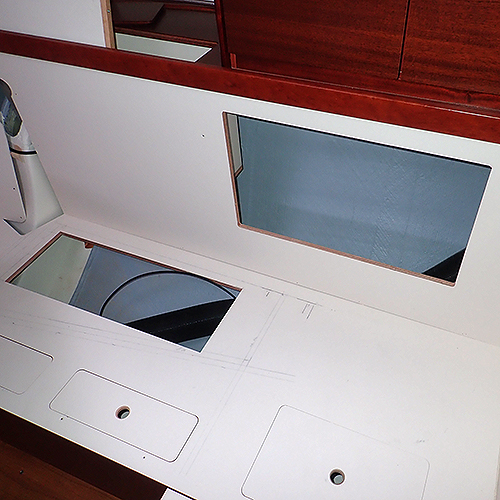 Birds eye view of the saloon and its new compartments. |
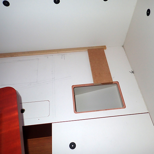
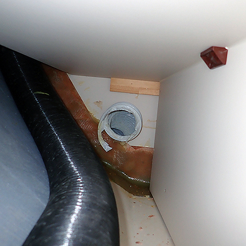
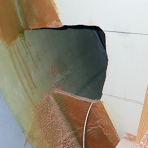
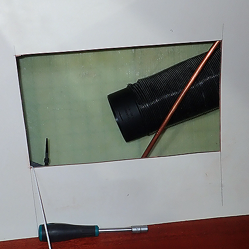
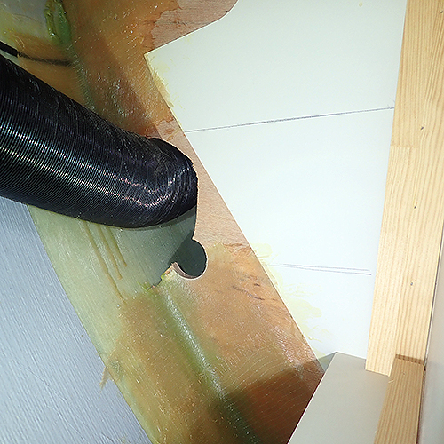 Before it was possible to start the insulation of the main pipe we needed to make the bulk head hole much larger.
|
 We used a hole saw to cut our the area we needed. Don't forget to use a vacuum cleaner as much as possible as the saw dust will otherwise land on the fridge compressor on the other side. |
 Inspection of the area with the fridge compressor and looking at the sterns direction |
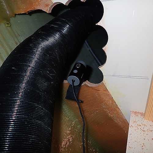
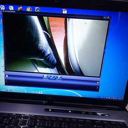 Using a webcam is quite handy when it comes to narrow places. we used it foremost to find out why we could not pull the pipe out. The answr was the plastic strap. You'll need a long arm and some kind of cutters. Go easy because the pipe will get dents if you press too hard. Dont pry, cut!
|
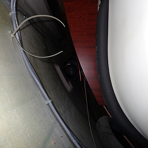 The pipe is out but the strap is still there... |
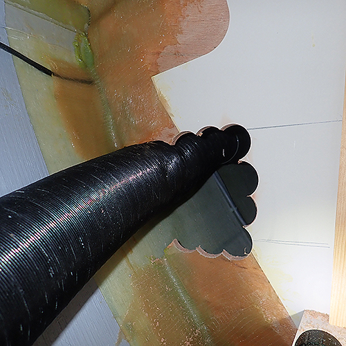
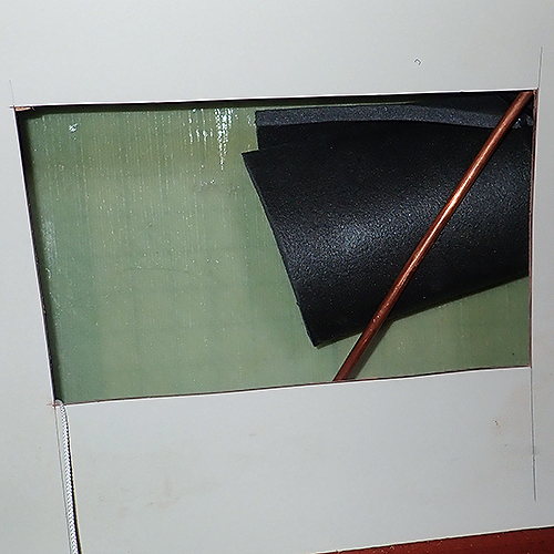
 Use a rasp or a file or rotating files to smoothen the edges of the hole so the insulation will not be damaged later on. |
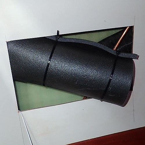
 Time to insulate the main pipe. Unloose it from the damper/Y-connector if you haven't already done so. Pull gently out the pipe to the saloon. Here it is very helpfull if you have a pair of hands to help you because its a quite narrow space you have to pull the pipe through. When you have managed to pull out the pipe as much as possible its time to go to the galley where you will need to cut off the pipe. |
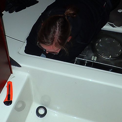
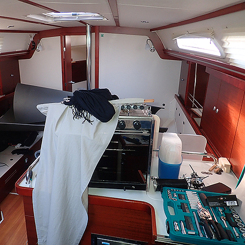 Remove the oven and don't forgett to remove/close the gas bottle first! |
 The cover behind the oven was little bit too small to work in so we made it sligtly larger. Be sure that you know where the gas pipe is so you don't cut it of. We used a Fein to cut out the hole. Observe the paper covering the gas pipe outlet to te left in the picture. |
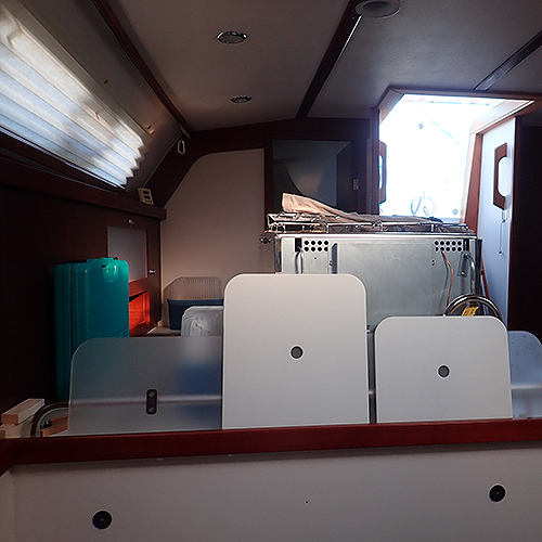 bild bort |
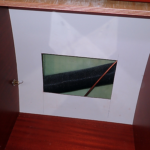 Bild bort |
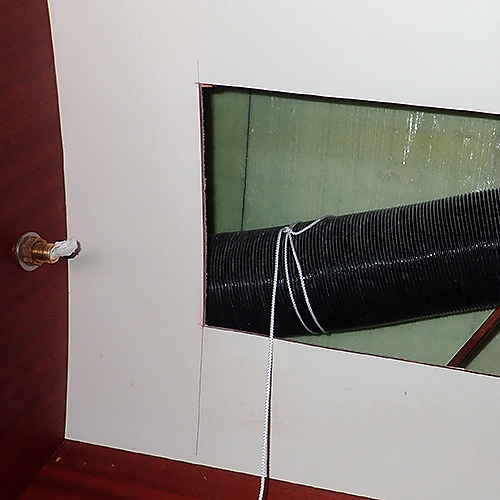 Start by tying a long string to the pipe. This is for pulling the pipe back later on so make a tight knot! |
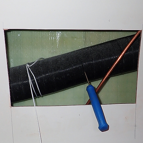 Cut the pipe in the middle of the holes width. |
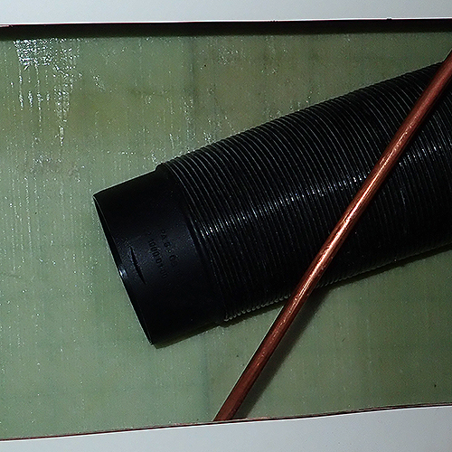 Add the splice tube in the remaining right side tube. |
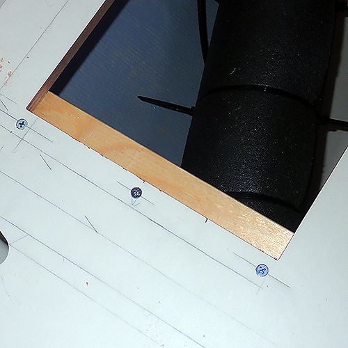
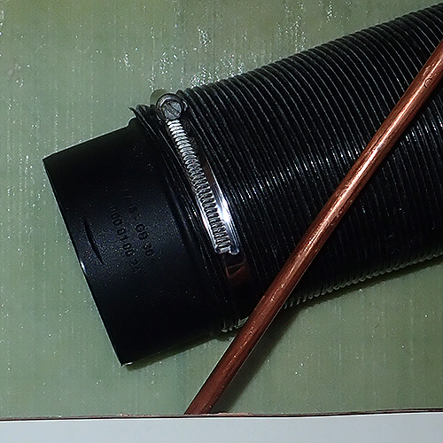 Add a hose clamp to keep the splice in its place. Measure how long piece of insulation you can have in the area right of the copper tube. |
 In the saloon, pull out the pipe and be sure that the string comes with it. |
 The string that you need to pull the insulated pipe back with into the galley. |
|
 Cut a piece of the insuilation according to your previous measures in the galley. |
 Make a roll of the insulation material, add straps but dp not tighten them yet too much. |
 Slide the insulation tube to the left of the hole |
 Grab the pipe... |
 ....and slide the insulation around it. The space here is quite narrow so be prepared to sweat and curse few times as you probably need to remove the insulation and adjust its lenght. |
 Nest step is to insulate the pipe in the saloon. Make a long tube but not full lenght of the pipe as you will otherwise not be able to handle the pipe properly in the upcoming steps. |
 Use the string you fitted previously and pull in the pipe from the slaoon to the galley. Join them together, slide the insulation into its position and wipe the sweat from your forhead. |
 Tuck the pipe upwards and get back to the saloon. |
 Fit the tube in its place,measure the lenght of it and cut a insulation tube. |
 Fit the tube in its place and... |
 ...enjoy the result of your struggle as nothing of this part of the job is easy. As said in the beginning, remove the table and make your work slightly more easier. |
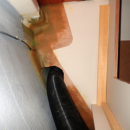
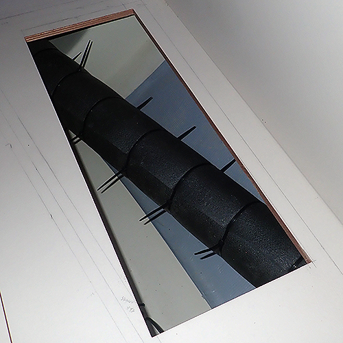
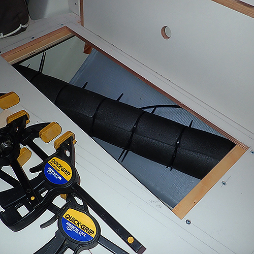
 Here you can see in the bottom of the picture how we insulated the pipe coming from the port side aft cabin. |
 GÖR OM DENNA BILD!!! You will need someone small and nimble person to do this part of the job. |
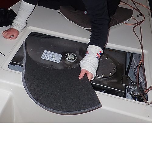
 The socks prevented from scratches and glassfiber splints. The surface under neath is not the smoothest one we can tell. |
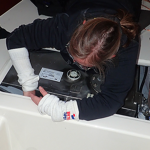
 To fit the insulation around the smaller pipe under the cabin, the one that provides the cabin with hot air was a smaller hell. You need to open all the ventilation grids etc and then do the insulation under the cabinette pretty much your eyes closed. |
|
|
|
|
|
Time to cloese things up. Instead of using some plywood we decided to go with a thin plastic as cover for the hole behind the oven. The plastic is much easier to handle than wood. Start by adding screws from the top and work your way done as you add preassure to the plastic. Take in consideration that the white surface is concave when you measure the covers size. |
 Close up of the cover and the ventilation holes. |
|
|
|

|
|
|
|
|