![]()
|
Aft windlass installation This was probably the most stressing installation we ever have done on our boat as it required drilling several holes, cutting out one big hole and trying to do all this in a very small cramped space. We made some serious mistakes in the beginning when we tried to fit the windlass when the boat was on land. We trusted the boats lines and angles too much and thought everything was level which it wasn't! So our strong advice is that you do all the fitting when the boat is in the water and hopefully not fully loaded. We started the whole procedure by making a jig out of MDF-board. The jig is basically made by copying the stainless steel windlass base when its put on the MDF and lines was drawn inside the chain and bolt holes. You also need to draw the outlines of the base so the jig is an exact copy of the base. Remember to write on the jig what is up and what is the inside and outside so you know how to place it on the boat. The jig was also later used to press epoxy filler on the inside of the transom so there would be a solid flat surface to seat the steel base. The jig was first covered with Gladwrap so the epoxy would not stick to it. Then we added lots of epoxy in places where we thought there would be gaps and then we pressed the jig against it and tightened the bolts. The bolts were covered in grease so the epoxy would not stick. When the epoxy had hardened we removed the jig, filled the remaining holes and gaps and ground off the sharp edges etc. When the windlass was in place the next step was to do all the electrical works. How we did that you find in the bottom of this page.
|
|
 1. Here we aligned the jig to the deck line which was the first mistake as the deck is not normally horizontal. Then we drilled the bolt holes one by one with a wood drill (the one with a point) till the point was visible from the outside and then we drilled the hole from outside. This was done in order to avoid larger cracks in the gelcoat. |
2.
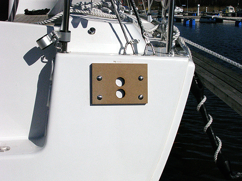
For some strange reason we decided that before we drill the last bolt
hole and the larger 35mm holes, we should place the steel base on the
outside and see how it looks . When we did this we realized that the
holes were totally misaligned and the last small hole was way outside
the base. We just had to stop the fitting and wait till the boat was in
the water. |
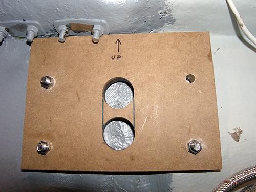
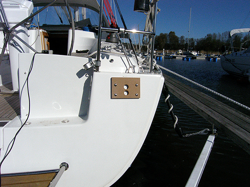
 3. By using two 35mm holes in the jig you will have a better starting point which will avoid the drill slipping compared to if we had made a full opening in the jig. Also, use a thick board for the jig as it gives you a longer "tunnel" which keeps the drill at the correct angle. |
4. Protective
wear
such
as
safety
glasses, dust mask, ear protection plus
protective
clothing was a must in order to avoid epoxy dust. The dust mask filter
was later changed to a carbon filter when we applied epoxy to the
transom from the inside. The fumes from the epoxy are a killer so be sure
that you also have good ventilation. |
5. A month
later or so we launched the boat and attacked the now very anxiety
filled task again. We started by filling all but upper right hole with
epoxy so we could do the drilling properly. We used to level the jig. My
wife was inside the boat all the time this sunny day and enjoyed the hot
spring weather. Be sure that your helper has lot to drink because it is
not easy to crawl back and forth into the transom compartment. |
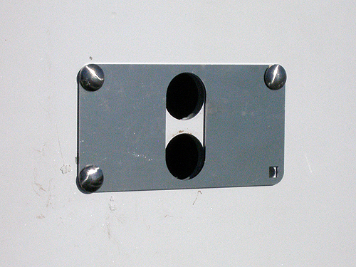
 6. When the first bolt was tightened we drilled the second upper hole and added a bolt. From this point on it was quite easy to drill the other two holes without having to worry that the jig was not in level. After the bolts were in place we drilled the two larger holes. |
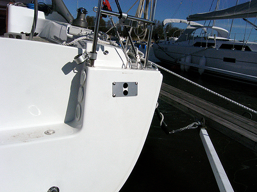 7. Before continuing with the removal of the remaining transom we tried the steel base in its place. It was a relief to see that it worked as we hoped.
|
 8. We first used a small pointy hole saw to cut out the remaining transom and finished it with a drill fitted with a rotating file. We used the steel base as a jig for the file. You have to be sure that the tunnel walls are at least 90 degrees or more so the rope and chain will pass though properly.
|
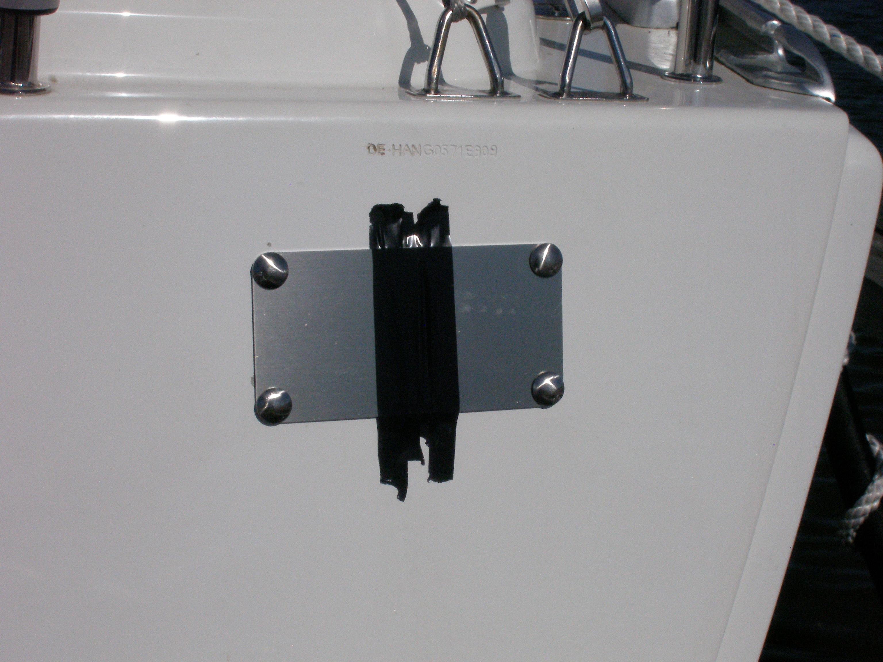 9. As we could not finish the job in one day we had to cover the hole with some duct tape for the night so there would not be any water in the "tunnel". |
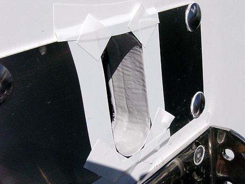
10. The edges of
the tunnel were later painted with gelcoat. The line that is visible in
the "tunnel" is the extra layer of epoxy we had to added between the
steel base and the inside of the transom. As you can see, it is a quite
thick layer we had to add. |
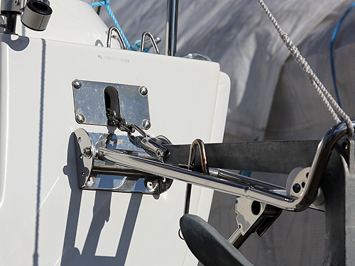
 11. The anchor holder was fitted slightly below the stainless steel fram for the rope hole of two reasons: The first one is quite obvious as the shelf inside is hanging lower than the hole and you need some space to use tools to fit the anchor holders plate. The second reason is that you the anchor arm must lean down little bit in order to have the anchor sliding down properly. The latter issue can also be adjusted by cutting the supporting strut shorter. In our case the anchor arm is little bit too upright and we need to give the anchor a push so it slides down. The positive with that is that when using the free fall mode we can release the chain and rope in advance and when getting closer to shore we just step on the swimming platform and give the anchor a push and it starts sliding down.
|
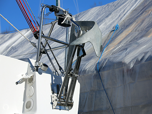
 12. The anchor arm folded down. The white rope is there to secure the arm to the push pit when in upright position and to ease the hoisting of the anchor arm. I will also act as a supporting strut from the above if necessary. |
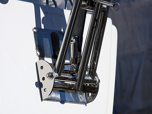
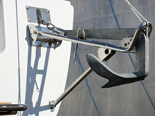 13. Here you can see how the supporting strut and its "shoe" is fitted. We chose to fit the "shoe" as low as possible which lead to that we had to cut the "shoe" slightly on the starboard side. See next picture.
|
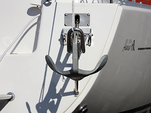 14. Here you see the "shoe" cutted as described in previous picture. You can also see how the anchor is aligned with the exit holes plate. |
 15. The anchor and its arm in upright position tied with the white rope to the pushpit. |
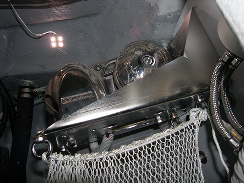 16. The winsch shelf from the side. As you can see we have fitted a mesh bag for the rope so it will collect the rope in one place.
|
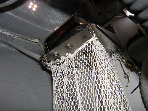 17. The mesh bag is tied to loop nuts that we added to the shelf. As there was holes already in the shelf no extra drilling necessary.
|
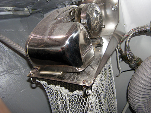 18. Just an different angle of the fitting. |
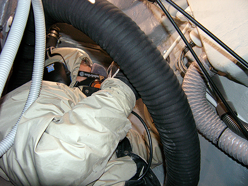
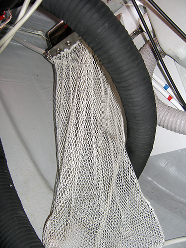 19. The mesh bag goes from the top to the bottom of the hull behind the exhaust pipe.
|
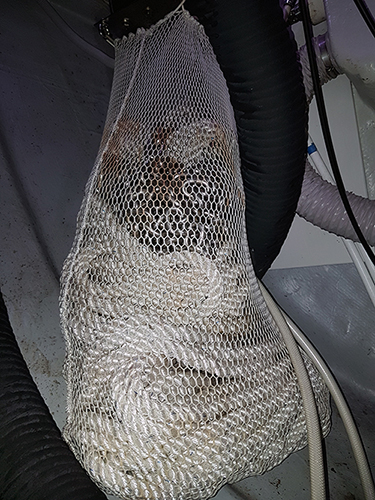 20. The mesh bag with 75 meter of rope and 4 meter of 8 mm calibered stainless steel chain on top of everything. |
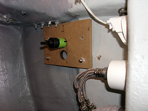
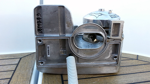 21. This is how the windlass looks underneath. Only three bolts needed to screw it to the shelf.
|
|
|
Windlass rocker switch
installation The windlass is now in place and the wireless remote works as it is supposed to. The next step was to connect a rocker switch as a backup. Since we are allergic to drilling holes all over the boat we wanted to place the rocker switch somewhere close to the steering wheel and in a place that could be easily repaired if we want to move the rocker switch later on. We chose to place the rocker switch on the steering pedestal console where we already had installed the switch for the electric winch.
|
|
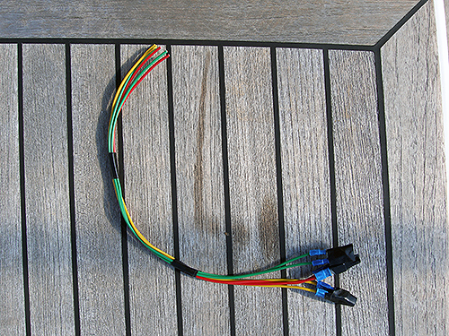
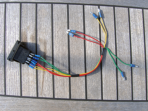
1. We started by preparing a set of cables that would be fitted to the
rocker switch. The reason why we choose to do it like this is that it
will be easier to remove the console later
|
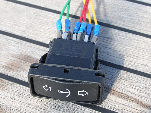
2. The cables connected to the rocker switch. |
 3. Close up of the rocker switch cables |
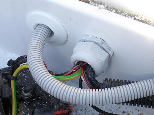
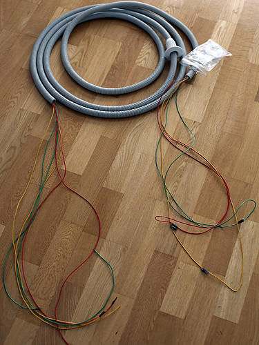 4. Next step was to prepare the wiring from the batteries to the steering pedestal. The grey flexible conduit protects the wiring and makes a neat installation.
|
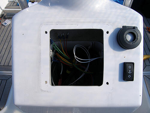
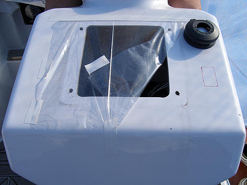 5. Then it was time to make the hole in the console. We used the rubber seal that comes with the rocker switch as a template and marked the position. Then we drilled some holes and cut the hole with a small saw blade and ground it nicely to get a good finish.
|
 6. Testing that the rocker switch and the rubber sealing fits as it should. |
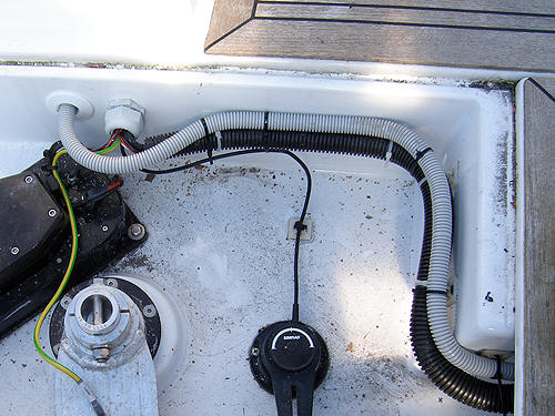 7. Next step was to fit the wiring from the inside of the boat to the steering pedestal. We have installed an electrical gland underneath the autopilot compartment in the aft of the boat in order to have a shorter cable run . It’s the same place where we feed the electric winch switch cabling from.
|
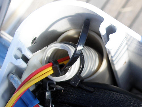
 8. We drilled a hole next to the other cable penetration and sealed it with SIKA flex, both around the hole in the fiberglass and where the cable conduit goes in the white cable gland. |
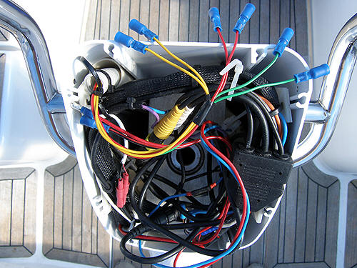
 9. It was not easy to get the wiring up in the steering column. First of all its narrow, then the grey conduit did not go as straight as it should and when it was in its place it was difficult to fit it so it would not get jammed to the moving parts of the steering system. So the solution was to find a rigid plastic tube that fitted in the upper left corner of the steering column and squeeze it there so it would not move. After that we fed the grey cable conduit from the bottom of the steering column (there are holes prepared for that in the bottom) through the white tube and locked it with a cable tie to other cables.
|
 10. When everything was set we crimped the female cable connectors to the wires. |
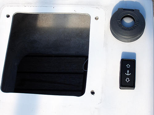
 11. The final result. On the top right is the electric winch switch and under it is the windlass rocker switch.
|
|
| Materials we used |
All information below,
product pictureas and tables by courtesy of Lewmar and Båtsystem. |
|
|
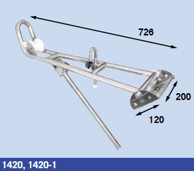
Båtsystem anchor holder
1420, adjustable, max 20 kg. This new model (for 2012) has a locking system that keeps the anchor in place better compared to the older model 1415. The locking pin needs something in its end so it will not slip out if you forget to tighten the screw. The package contained two of these screws. When we lost the first one during week one we understood why there was two of them. To avoid loosing the second one we rounded the top threads of the screw with a hammer and screw driver so it will not be possible to fully unscrew it. |
|
We learned from Liros that there is one crucial thing to think about when you use a rope with a windlass and it is that it has to be heat set. If it is not, it will be too soft for the winch and can slip. Heat setting a rope will make it firmer and easier for the windlass to grip. |
|